Q1 - What is a P&ID diagram?
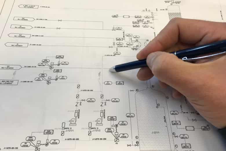
A P&ID diagram, or Pi A P&ID diagram, or Piping and Instrumentation Diagram, is a critical engineering schematic used primarily in the process and manufacturing industries. It provides a detailed visual representation of a system's piping, instrumentation, and other components. P&ID diagrams use standardized symbols and conventions to illustrate equipment, valves, pumps, instruments, pipes, and other elements in a complex industrial process. They serve multiple functions, including design, construction, operation, and maintenance, and are instrumental in helping engineers and operators understand how different components interact within the system. These diagrams are essential for the safe and efficient operation of industrial processes.
Q2 - How do you create a P&ID Diagram?
Creating a P&ID diagram involves several key steps. It begins with gathering all pertinent information about the process or system, such as equipment specifications, flow rates, and control strategies. Specialized software, like AutoCAD, Microsoft Visio, or dedicated P&ID software, is used to create the diagram. The process typically involves placing standardized symbols representing equipment, valves, pumps, instruments, and pipes onto the drawing canvas. These components are then connected with lines to illustrate process flow, with labels indicating tag numbers and size. It's crucial to adhere to industry standards and guidelines to ensure consistency and clarity. Review and verification by relevant stakeholders is essential to correct any errors or oversights before finalizing the P&ID for use in the system's design, construction, and operation.
Q3 - What us the difference between P&ID and schematic diagram?
The primary difference between a P&ID (Piping and Instrumentation Diagram) and a schematic diagram lies in their purposes and the level of detail they provide. P&ID diagrams are focused on representing the process and instrumentation of an industrial system, emphasizing the interconnection of pipes, equipment, and instrumentation, with a strong emphasis on depicting flow and control. They use standardized symbols and focus on the physical aspects of the system.
Schematic diagrams, on the other hand, are more versatile and can encompass a broader range of applications. They are typically used in electrical or electronic systems to represent the connections and functions of components, emphasizing the electrical or logical relationships rather than physical layout. While P&IDs are specific to process industries and focus on fluid and control systems, schematic diagrams can be used in a variety of engineering disciplines and are not limited to a specific domain.
Q4 - Which software is used to draw P&ID?
Several software tools are commonly used to create P&ID diagrams, and the choice often depends on the preferences and needs of the engineers or the organization. Some popular software options include AutoCAD P&ID, Autodesk Plant 3D, Microsoft Visio, SmartPlant P&ID, and P&ID Designer. These software applications offer libraries of standardized symbols, templates, and drawing tools that simplify the creation of P&ID diagrams, making the process more efficient and accurate. The selection of software can also be influenced by compatibility with other design and engineering software used in a particular industry or company.


