|
As you have read, there is more than one standard that defines the different symbols that allow you to design a P&ID diagram.
As always, if we want to define our internal standard of plant,
it is better to read the content of all the standards and select the best of each one of them.
It is also important to take as a reference standards that ensure an update of their content based on the evolution of technology,
this ensures that our reference p&id standard always provide a solution to the different representation problems that will arise over the years.
Whatever the choice of a reference standard is a decision that will condition the plant documentation for a long period of time,
this implies that the change of standard or reference will be complex or practically impossible.
As reference, over 8 years after the release of ANSI/ISA-5.1 in 2009 most companies are still using
only PIP PIC001 or ISA-5.1 1984 for their P&ID diagrams.
Other related articles :
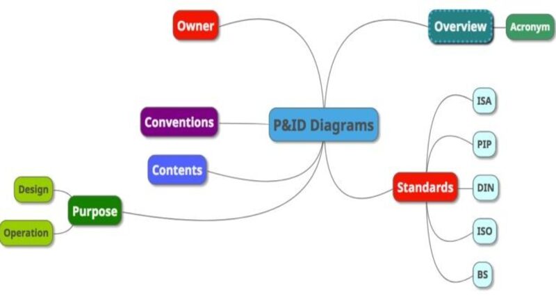
 P&ID Diagram Basics PART2 P&ID Diagram - Mindmap showing the contents of the article
This article is a summary of the different existing standards on the symbology and methodology to create
a P&ID. Some of these standards, such as the ISA, are more than 20 years old and have been considered, in the absence of other documents,
as de facto standards in the international industry.
As a general rule, the standards mentioned in this article are used as reference documentation in the process
of creating process plant standards. Each plant/organization adapts the content of these standards
to its own internal standard by selecting the most significant material that best suits its purposes,
thus generating its own internal rules.
If, on the other hand, we do not have these internal rules and there is no established standard in the plant / organization,
normally the symbology is usually based on the ISA-5.1-2009 (R1992) standard, which is an excellent,
flexible document that defines, primarily , instrument symbolism.
P&ID diagrams must be designed systematically and uniformly within a company. Firstly, the development and implementation of a P&ID project
always involve professional engineers from various departments.
The revisions on the P&ID diagram allow to reflect the changes of the process and
it is essential that they follow some rules whenever a revision is necessary. A P&ID diagram with incoherent formats leads
to confusion and misunderstandings on the part of process technicians.
Based on the above reasons, a complete set of standards must be determined before the development of P&ID diagrams,
either to create a P&ID diagram by hand or on a computer.
These standards define the format of symbol and identification label for each component of the P&ID diagram.
P&ID diagram symbols are graphical representations for process components, e.g., equipment, piping, and instruments.
Identification labels are a combination of letters and numbers used to uniquely recognize a process item.
Currently, there are many standards for instrument symbols and lettering abbreviations of the P&IDs.
The most common ones comprise the PIP, ISA, ISO, BS, and DIN standards.
Below are the different organizations that have developed guides or standards on the P&ID symbology:
- ISA Instrument Society of America
- DIN Deutsches Institut für Normung
- PIP Process Industry Practices
- ISO International Standards Organization
- BS British Standard
|