Introduction to Instrumentation
Process control is today a fundamental part of the production process. Through process control we are able to produce our products in line with our quality, cost, environment and safety standards.
This article provides a basic introduction to process control based on the differentiation between an open control loop and a closed control loop. This fundamental idea is part of the pillars of process control.
In the second part of the article we talk about the mythical current loop and the reasons why it is still a valid and current means of communication.
The article ends with a small reference to instrument calibration.
Download your free PDF file about introduction to instrumentation!
We have prepared this complete pdf so that you have all the information we give in this article and you can share it, discuss it with your colleagues and use it professionally.
We consider that it is better to have a well-formatted text that includes all the key concepts explained in this publication ready to share or save for later use.
- Rating: 4.6 - 83 reviews
You can share this article through:
1.Control System
Measurement and control constitute the brain and nervous system of any modern plant.
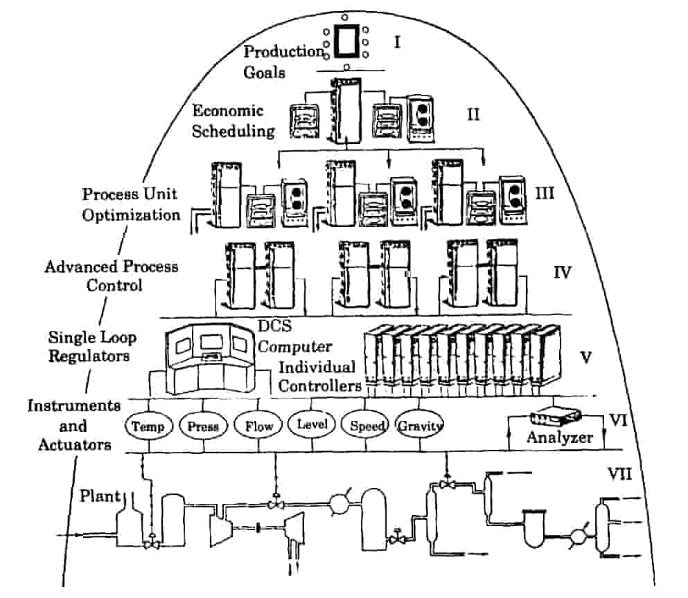
Control systems are a fundamental part of industry and automation. They are a set of mechanical, electrical and electronic equipment used to enhance production, efficiency and safety.Typically, control systems are based on control loops.
The measurement and control system monitors and regulates processes that would otherwise be difficult to operate while maintaining quality, cost and safety requirements.
The control systems must achieve the following objectives:
- They must allow to operate the process in a transparent way, implementing functions that improve the management and control of the Plant.
- They must display integrated and reliable information, and in case of system or process error they must be stable and robust.
- Ideally, they should improve the quality of the product produced by reducing the variability of the measurements under control.
Process control is necessary in modern industry for:
- Keeping businesses profitable.
- Improve product quality.
- Reduce atmospheric emissions.
- Minimize human error.
- Reduce operating costs.
2.Types of control systems: Open Loop / Closed Loop
2.1 What is an open loop?
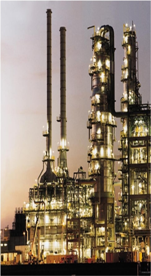
An open loop system is a type of control where the output of the system depends only on the input. These systems have no feedback.
In open loop, the system does not compare the measured variable with the desired value (set point). It is a system in which there is no measuring instrument.

It is a simple system and is affected by disturbances.
2.2 What is a closed loop / feedback loop?
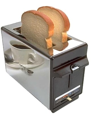
A closed loop system is a type of control where the output of the system depends on the input and the output. These systems feed back the current output of the system and this information is taken into account when calculating the new output value.
In closed loop, the system does compare the measured variable with the desired value (set point). It is a much more complex system than the open loop and is less affected by disturbances.
In process control, the basic objective is to regulate the value of a quantity, this desired value is called set point (SP), we also have a way to measure the value of the variable to be controlled continuously (PV) and we also have a way to compare this measured variable with the desired value (ERROR).
Finally, a method of acting or influencing the measured variable (MV) is needed.
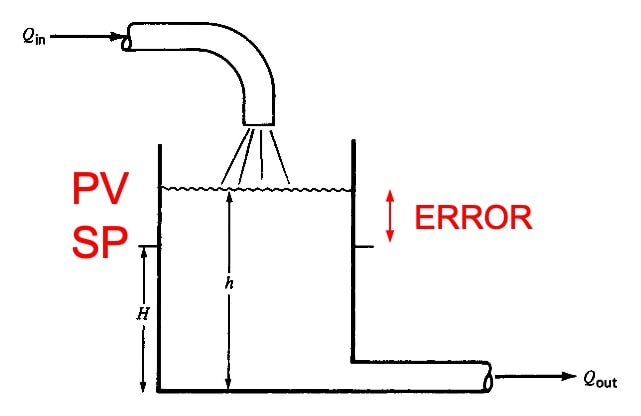
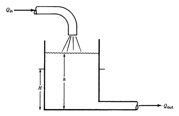
This picture shows a system consisting of a tank with an inlet liquid flow Qin, and an outlet flow Qout.
The liquid in the tank has a height or level equal to h. The formula for Qout is Qout = K*√(h), since the flow rate out of the tank depends on the height of the liquid h (Torricelli's Theorem).
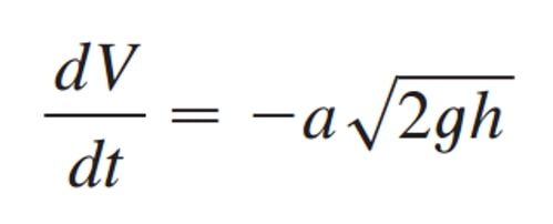
If h is very small the Qout will be smaller than Qin and then the liquid height will increase. If the liquid height increases it will cause Qout to increase so that we will reach a point where Qout will be greater than Qin and the liquid height will decrease.
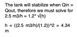
There is a value of h at which Qout is equal to Qin -at this point we say that the level is self-regulating.
Looking at the tank in the image above and taking into account the following data:

At what liquid height will the tank be self-regulating?
2.2.1 Manual versus Automatic Closed Loop
We have said that a method of acting or influencing the measured variable (MV) was necessary.
If we assign a person to control the level (height) of the tank, he/she can adjust the height by opening and closing the outlet valve that regulates the flow Qout, so that the level can be regulated.
The controlled variable is still the level (SP), but now the height of the tank depends on an action manipulated by a person (MV) (MANUAL CLOSED LOOP).
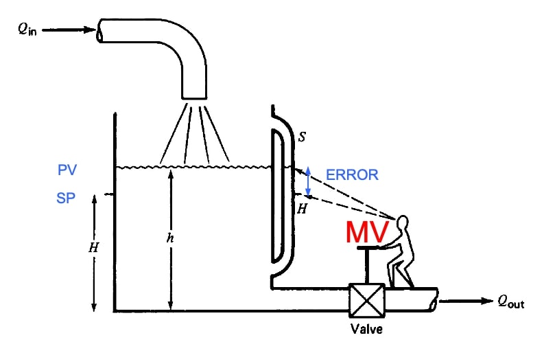
Why does the tank level fluctuate?
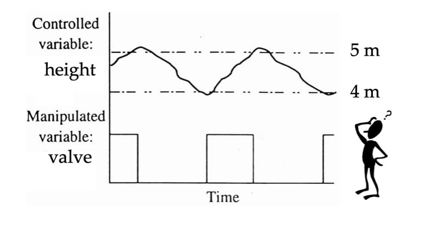
Do you consider it stable enough as a variable of a chemical process?
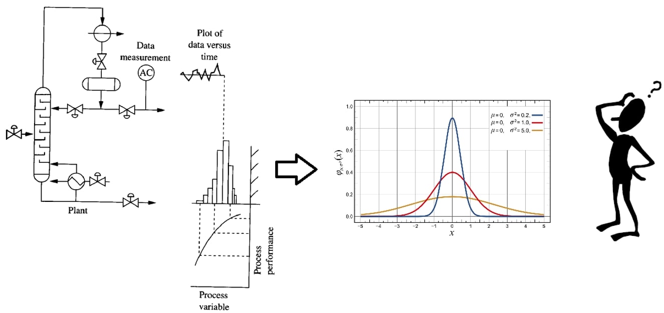
If we replace the person with an automatic system (AUTOMATIC CLOSED LOOP) we can obtain a more precise control of the level.
The height of the liquid level in the tank is measured by a sensor (mechanical or electronic) and a controller calculates the difference between the measured value (PV) and the set point (SP) and generates a signal to the actuator to open and close the flow controlled outlet valve Qout (MV).
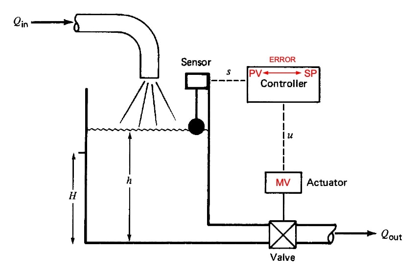
From what has been explained so far, a feedback control system seems to have at least 3 basic elements:

How do we select the sensor position?
The position and type of sensor will depend on the loop we want to control, usually the position of the sensor is located near the influence of the output of the control system, so the control action can vary a measure and this measure can be used as feedback information.
What is a typical final element for a chemical process?
Typical end elements are usually valves. These can be control valves or ON/ OFF valves. Frequency inverters or other electrical, pneumatic or hydraulic devices can also be used.
What about the typical sensor?
Pressure is the ultimate measurement. With a pressure measurement it is possible to calculate the level, the flow rate and the pressure itself.
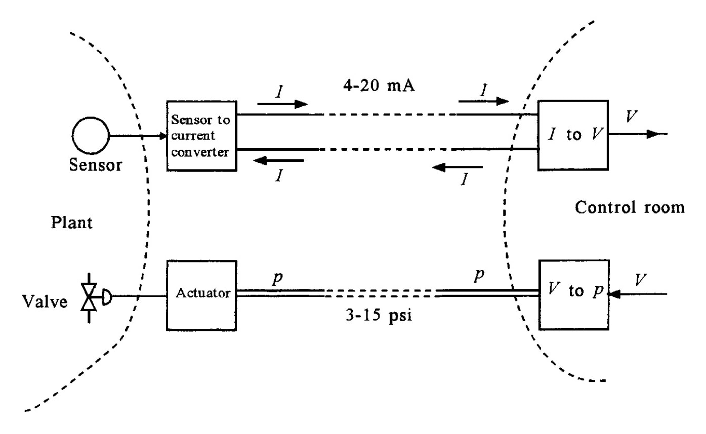
The following diagram shows the elements of a closed loop:
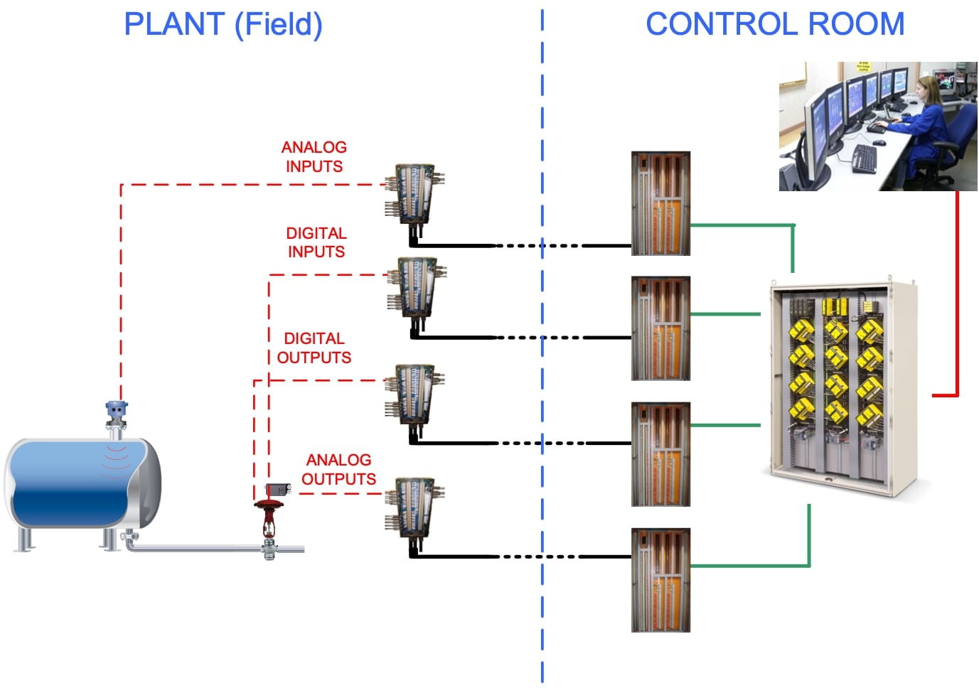

3. Standard instrumentation signal levels
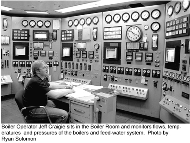
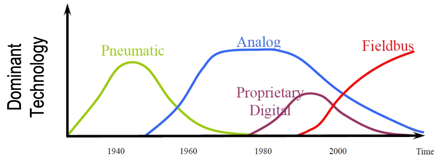
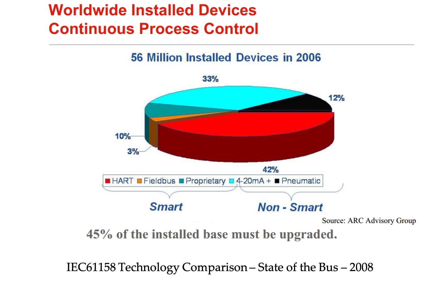
Prior to 1960, instrumentation in the process industries used pneumatic (pressurized air) signals to transmit measurement and control information almost exclusively.
These devices make use of mechanical force balance based elements to generate signals in the range of 3 to 15 p.s.i. as an industrial standard.
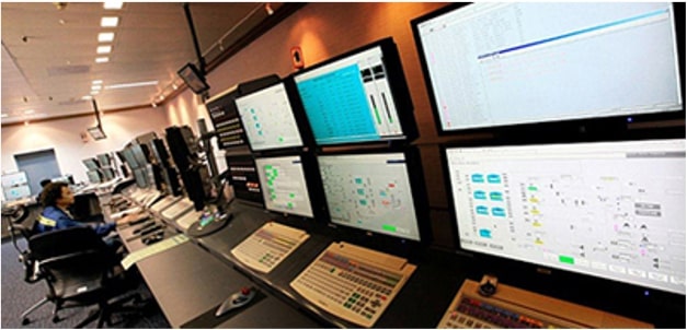
Since 1960, electronic instrumentation has become widespread (4 to 20 mA).
Recently, field bus type signals have become more common.
The transmitter converts the sensor output signal to a signal suitable for the controller input (4..20mA).
They are normally designed to act in direct action.
Although, as we have said, electronic instrumentation has spread, analogue instrumentation is still predominant, so we consider it interesting to dedicate a section to describe how it works.
3.2 Current Loop / Analogue
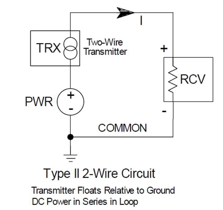
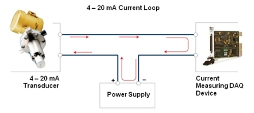
The purpose of a current loop is to transmit the signal from the analogue sensor over a certain distance in the form of a current signal, up to 3 kilometres.
The explanation is the following, the sensor varies the sum (intensity) depending on the measurement of the variable it is measuring. As an example, if we measure the temperature through a transmitter with range 0 to 100oC, it will consume 20 mA when the temperature reaches 100oC and 4 mA when the temperature reaches 0oC.
Advantages:
- Signal accuracy is not affected by voltage drop.
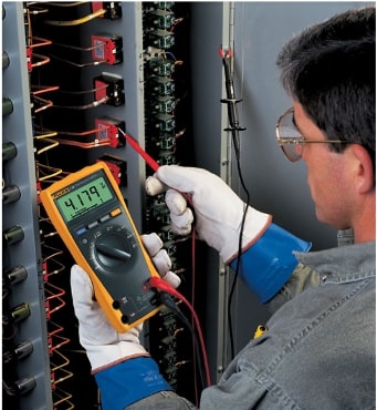
- Working with a minimum of 4 mA allows to detect problems in the loop.
- It is not necessary to have specialized training to carry out the installation/maintenance of this type of loop.
Disadvantages:
- Point-to-point communication only.
- A controller is required to perform the process control.
- There is no diagnostic information from the devices/sensors.
4. References:
- ANSI/ISA-50.1-1982 (R1992) formerly ANSI/ISA-S50.1-1982 (R1992) Compatibility of Analog Signals for Electronic Industrial Process Instruments
- LIPTAK,B. (2003) Instrument Engineers Handbook.Process Measurement and Analysis
- BEAMEX (2012) Ultimate Calibration
Another articles that may interest you:
- Do you want to continue learning about Instrumentation? Discover our new guide on the static and dynamic characteristics of instruments in Instrument Selection Principles.
- In the Instrument Simulation Laboratory you have a tool to see the relationship between a tank level measurement located in the field and its visualization in the control room.
- A complete list of the indispensable books that every professional in process control engineering must have, with prices and direct links to buy them if you want.
- Orifice Plate Calculator-Find Orifice Size is an useful tool to calculate the size of an orifice plate.
- Learn about the compensation flow calculation formula or equations in "Pressure and Temperature Flow Compensation Formula."
Any question?
If you have any question regarding this article, please don't hesitate to get in touch ... Anyway you can have a look at our frequently asked questions page, there you will find a solution to the most common questions.