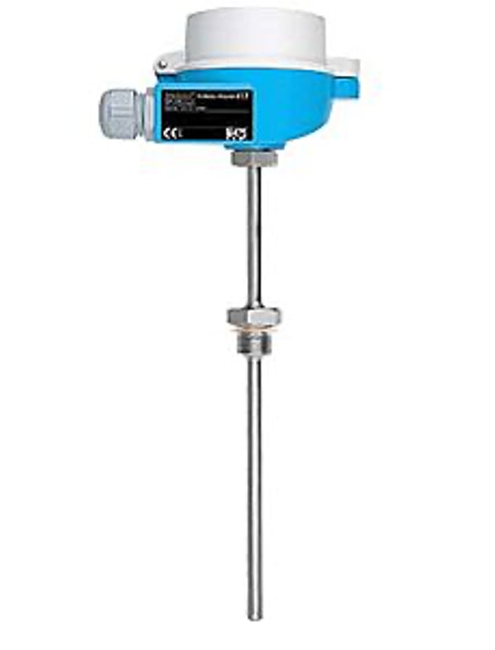
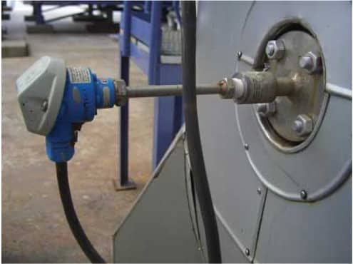
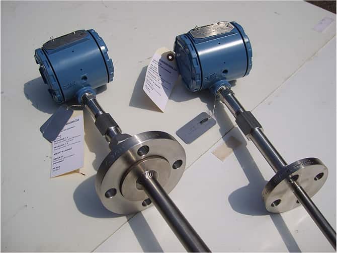
Temperature Measurement
Temperature measurement is one of the most common and most important measurements in industrial processes.
Classical kinetic theory represents heat as a form of energy associated with the activity of the molecules of a substance. These tiny particles of all matter are supposed to be in continuous motion generating heat. Temperature is a measure of this heat.
- Rating: 4.7 - 67 reviews
You can share this article through:
Download your free PDF file about Temperature Measurement!
We have prepared this complete pdf so that you have all the information we give in this article and you can share it, discuss it with your colleagues and use it professionally.
We consider that it is better to have a well-formatted text that includes all the key concepts explained in this publication ready to share or save for later use.
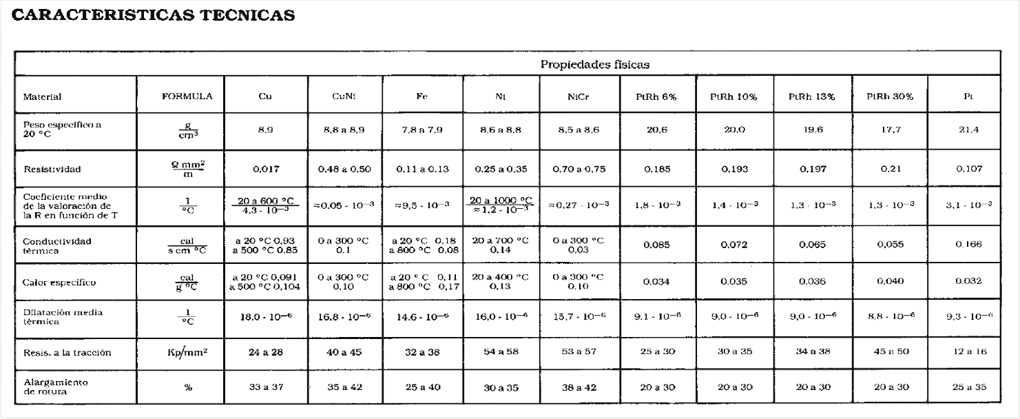
1. Technical Characteristics
2. Types of temperature measurements
There are several measurement scales F,C,K,R based on different reference points. In 1887 the IPTS was established, the last revision dates from 1990.
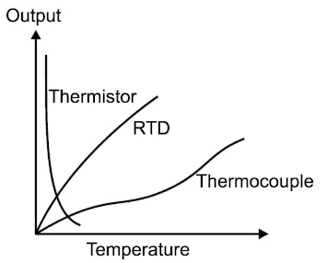
Depending on the measuring principle, continuous temperature measurement can be divided into two types:
2.1 Thermocouples
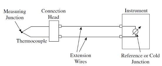
A thermocouple is a device capable of converting heat energy into electrical energy. Its operation is based on the discoveries made by Seebeck in 1821 when he circulated electric current in a circuit formed by two different metals whose joints are kept at different temperatures. This current circulation is due to two combined thermoelectric effects:
- The Peltier effect that causes the release or absorption of heat at the junction of two different metals when a current flows through the junction.
- The Thompson effect which is the release or absorption of heat when a current flows through a homogeneous metal in which there is a temperature gradient.

For temperatures below the phase change point the value of alpha is normally small, so the PEF is proportional to the temperature difference.
2.1.1 Thermocouple types by material
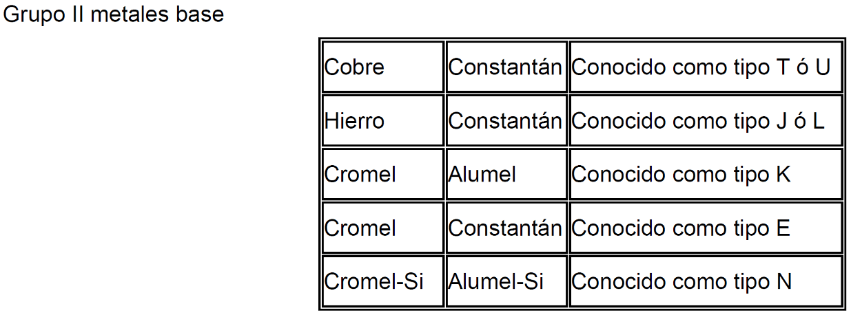
We can consider 8 types of basic thermocouple types T,J,K,E,N,R,S and B (listed in order of temperature). Their chemical composition is different for each of them. There are also other less used types such as Tungsten / Tungsten-Rhenium.
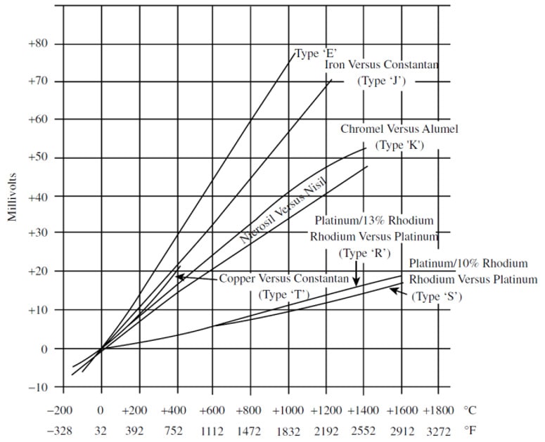

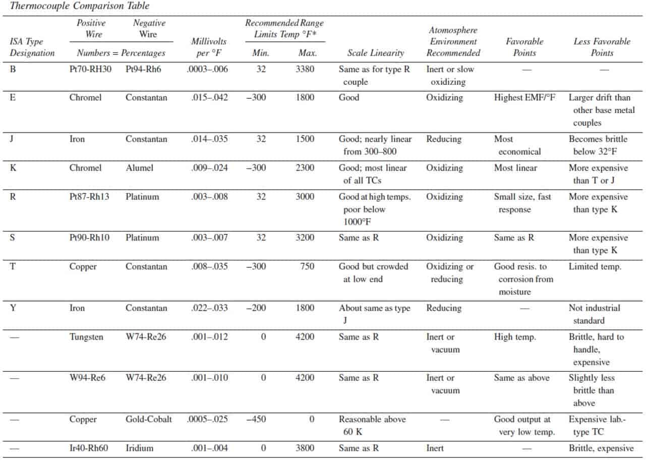
Thermocouples of types R, S and E are used in oxidizing atmospheres and working temperatures up to 1500°C. If the atmosphere is reducing, the thermocouple must be protected with a sealed ceramic tube. The type E thermocouple can be used in vacuum or in an inert or mildly oxidizing or reducing atmosphere. This thermocouple has the highest e.m.f. for temperature variation and can be used to measure temperatures from -200 to +900℃.
The T type thermocouple has a high resistance to corrosion by atmospheric humidity or condensation and can be used in oxidizing or reducing atmospheres. It can measure temperatures from -200 to +260oC.
The type J thermocouple is suitable for atmospheres with little free oxygen. The oxidation of the iron wire increases rapidly above 550℃, and a larger wire diameter is necessary up to a limit temperature of 750oC.
The type K thermocouple is recommended for use in oxidizing atmospheres and at working temperatures between 150 and 500℃. It should not be used in reducing or sulfurous atmospheres unless it is protected with a protection tube.
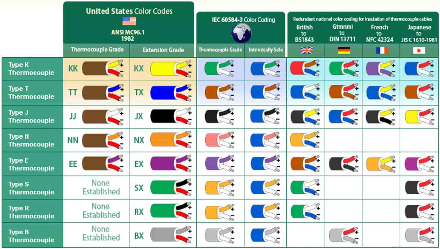
COLOR CODING FOR INSULATION OF THERMOCOUPLE CABLES:
2.1.2 Thermocouple Compensation
When the thermocouple is connected to any measuring instrument, a new VJ2 thermocouple is generated.
The most usual method is the cold junction compensation built into the instrument's amplifier.
The temperature at the joint is measured by a second measuring instrument. The output of this second instrument is used to calculate the voltage required ( Vrjc ) to counteract the effect of the compensating junction.
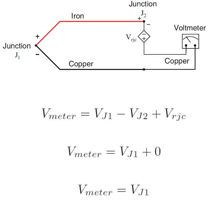
The connections between the compensation cable, the thermocouple and the instrument must be perfect, without splices in the compensation cable, using the correct wire and the whole installation must avoid the close passage by heat sources (the Thompson effect appears), if these recommendations are not complied with, direct current thermal stresses appear which give rise to a displacement in the calibration of the instrument.
The thermocouple is susceptible to industrial electrical noise because during operation it can generate voltages of 2 to 50 mv and is in an environment where large electrical machines can create hundreds of millivolts in the connecting cable. On the other hand the thermocouple working as an antenna can pick up electromagnetic radiation from radio television and microwaves. Hence it is required that the connecting wires are twisted together and inside a metal sheath which is grounded, that the measuring junction is grounded. In the case of the isolated connection, the assembly must be perfectly shielded and grounded, and the amplifier must have a good signal/noise ratio.
2.1.3 Thermocouple Advantages
- Low cost
- Small, they can be welded to a pipe.
- Used to measure high temperatures.
- Wide range (-210 to 2338℃ and mechanical resistance.
- Reasonably stable.
- Span minimum 25℃ for E,J,K and T types; 200℃ for S and R types.
- Accuracy: Sum of Thermocouple + Extension cable+transmitter, typically 1 to 2.8℃.
- Lower time constant than RTDs, fast response.
2.1.4 Thermocouple Limitations
- Non-linear elements, requires polynomial conversion through the signal conditioning system.
- They have low sensitivity (μV/℃) and need the reference temperature.
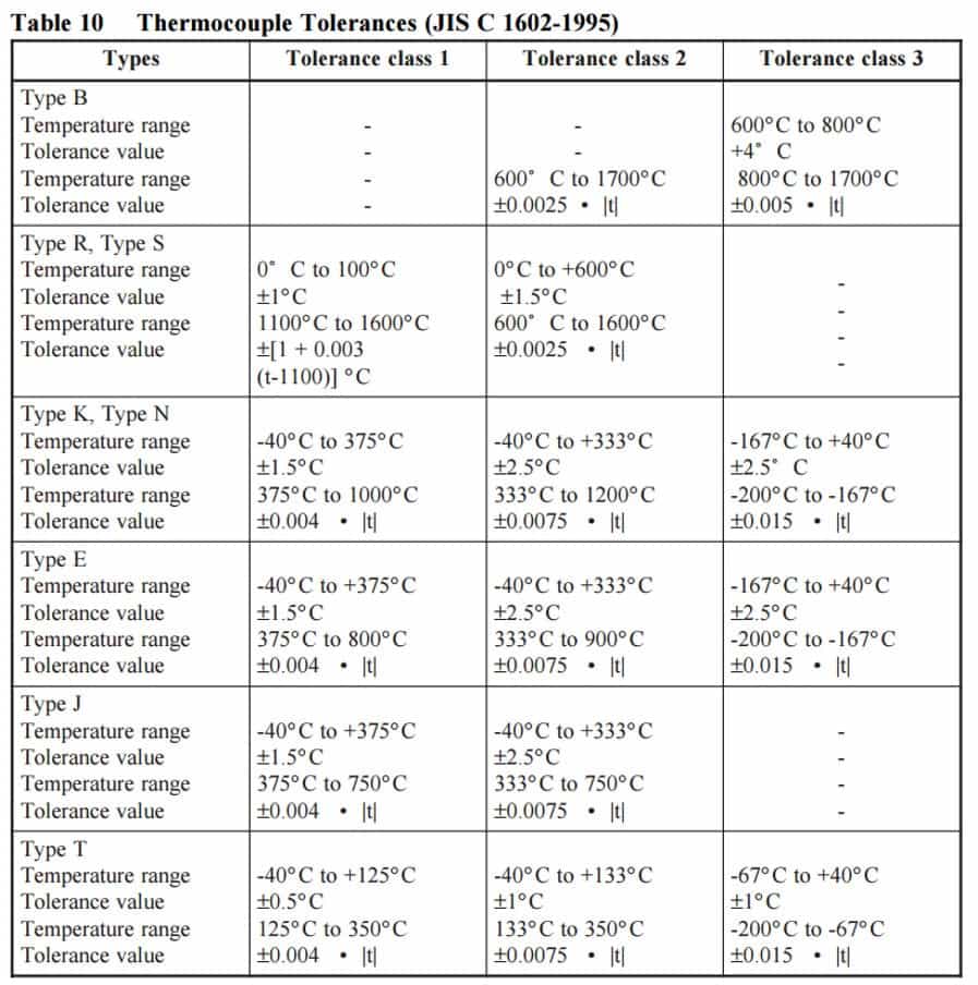
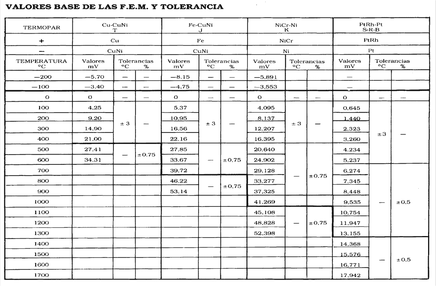
2.1.5 Thermocouple Tolerances
2.2. Thermoresistances (RTD)
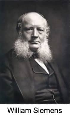
The tendency of electrical conductors to increase their electrical resistance with increasing temperature was first described by Sir William Siemens in 1871.
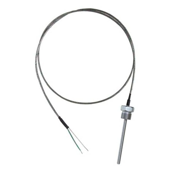
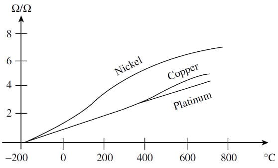
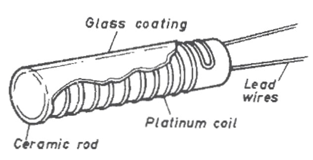
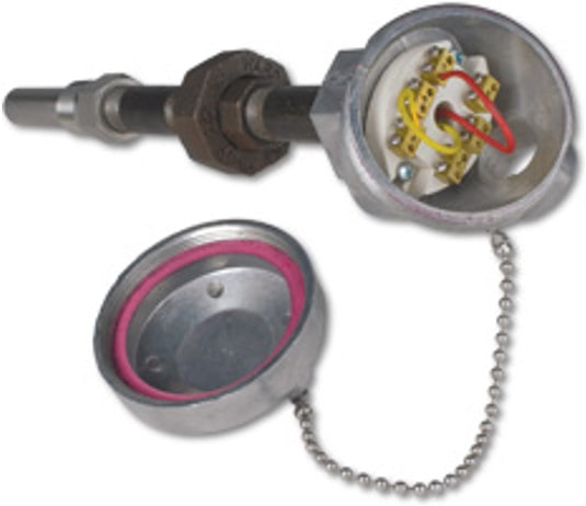
The resistive temperature detector is based on the variation of the resistance of a conductor (Ni, Cu, Pt) with temperature. Platinum is the material with the best performance:

Platinum has a high resistivity, for the same ohmic value, the sensor mass will be lower, so the response will be faster. It has major span and a very linear and low sensitivity.
IEC 751 specifies the relationship between temperature and resistance for industrial platinum thermometers. The relationship is defined by the Callendar-van Dusen equation:


2.2.1 Thermoresistance Process Connection
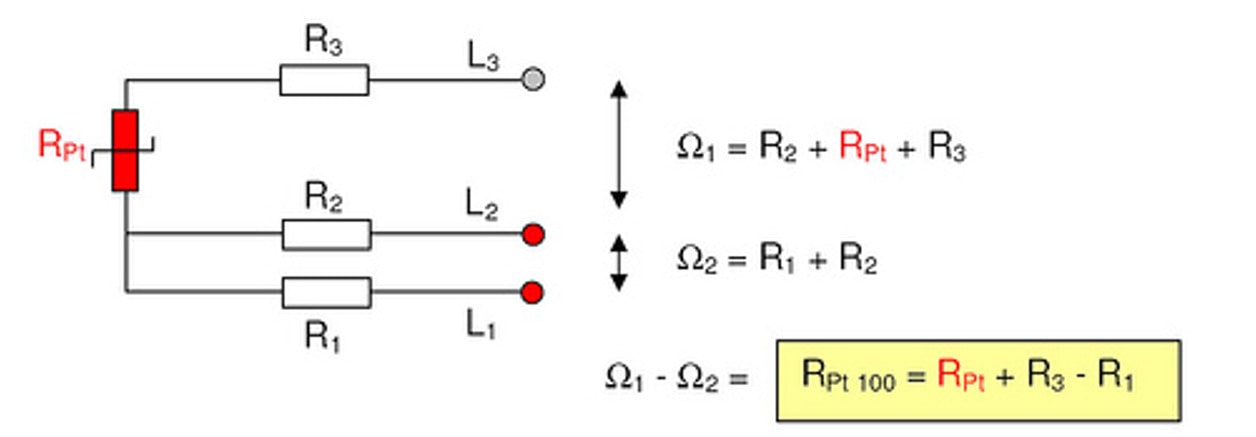
There are 3 connection modes for the Pt100 ( 2 wire connection, 3 wire connection and 4 wire connection), each requiring a different reading instrument:
2 wire connection: The easiest (but least recommended) way is with only 2 wires. The resistance of wires R2 and R3 is inevitably included in the total measured value.

3 wire connection: The most common mode is with 3 wires, it solves the problem of the error generated by the wires quite well. If the resistance of the 3 wires is identical, and only then, the value of the resistance RPt can be measured.
4 wire connection: This is the most accurate way. The transmitter generates a constant current (0.1-1mA) through wires L1 and L4. The Digital Voltmeter has a minimum input impedance of 10 MOhm. The current flowing through the voltmeter (DVM) is very small which means that the voltage drop in resistance of wires R2 and R3 is practically zero.

2.2.2 Thermoresistance Advantages
- Range : from -200℃ to 850℃.
- Accuracy : A ±0.03℃ B ±0.3℃.
- Long stability.
- Good sensitivity.
- They use standard copper connections.
- They have higher accuracy, repeatability, stability and sensitivity than CT scans.
- Depending on the accuracy they can measure hundredths of a degree.
- High sensitivity 0.1 to 10 Ω / ℃.
2.2.3 Thermoresistance Limitations
- Self-heating generates a constant error in the measurement.
- High cost.
- Larger than a CT scan.
- Slow response compared to a CT scan.
2.2.4 Thermoresistance Tolerances
Due to the fact that the resistivity coefficient varies with temperature, the standard defines manufacturing tolerances for probes, generating 2 different classes (A, B).
Class B is normally used for industrial applications, Class Ais used for special applications.
It is the only measurement that has an accepted standard defining accuracies and tolerances.
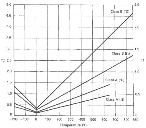
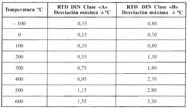
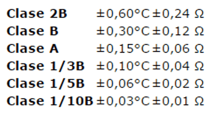
In 1995 IEC 751 establishes 6 tolerance classes:
3. Temperature Measurement Selection Criteria
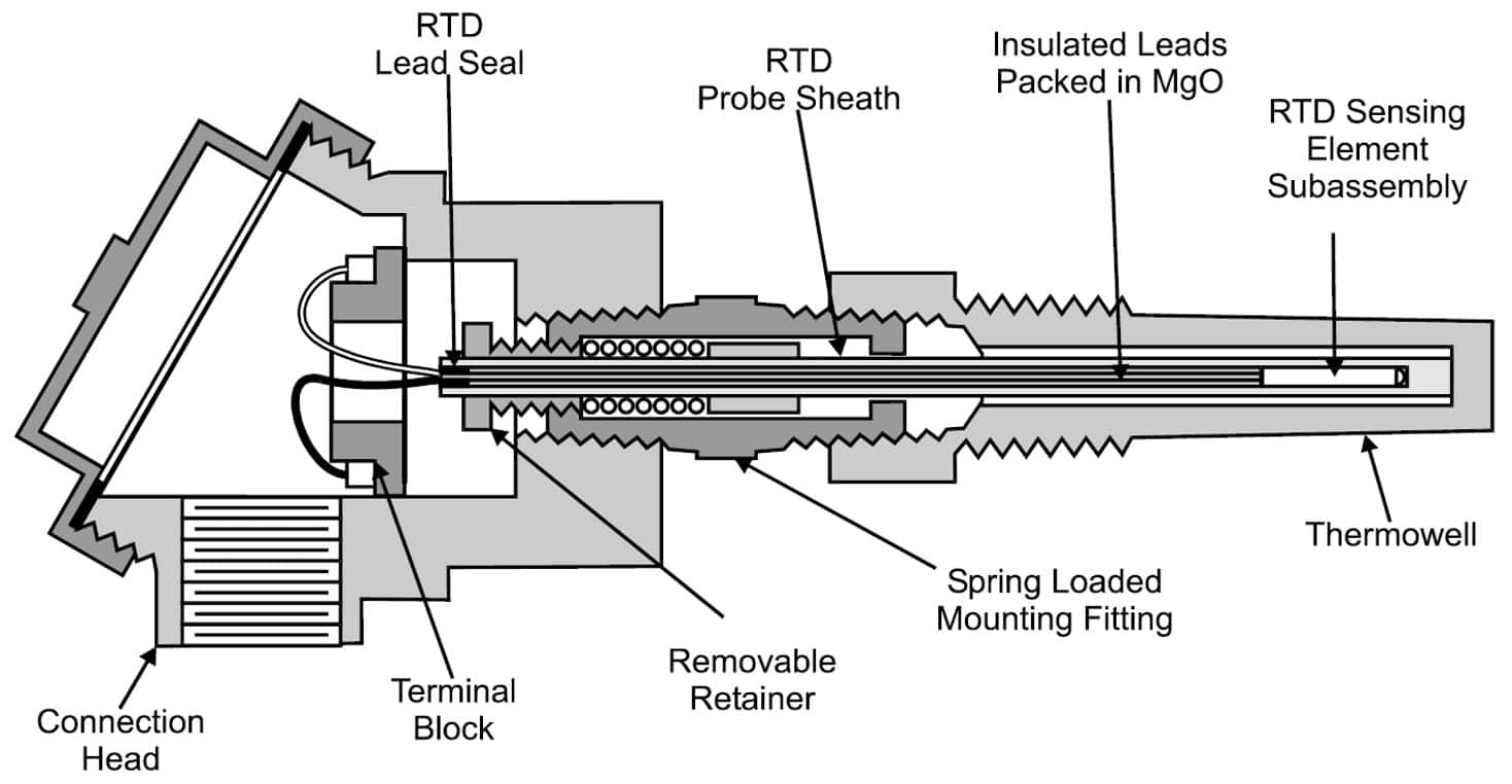
Both in Thermocouple and in RTD the connection to the process requires the installation of additional elements to protect the sensor (thermowell).

The installation of the thermowell has not been taken into account, which usually means in most cases a tripling of the measurement value (approx.).
4. Suppliers List
- ABB (www.abb.com)
- Foxboro/Invensys (www.foxboro.com/temp)
- Honeywell (www.iac.honeywell.com/ichome)
- Hukseflux (www.hukseflux.com)
- Kamstrup (www.kamstrup-process.com)
- Mathis Instruments Ltd. (www.mathis.unb.ca)
- Moore Industries-International Inc. (www.miinet.com/products/ca_temperature.shtml)
- Rosemount/Emerson (www.rosemount.com/products/temperature/)
- Siemens (www.sea.siemens.com)
- Yokogawa (www.yokogawa.com)
5. References
- ANSI/ISA-50.1-1982 (R1992) formerly ANSI/ISA-S50.1-1982 (R1992) Compatibility of Analog Signals for Electronic Industrial Process Instruments.
- LIPTAK,B. (2003) Instrument Engineers Handbook.Process Measurement and Analysis.
- BEAMEX (2012) Ultimate Calibration.
Another articles that may interest you:
- Orifice Plate Installation Guidelines is a necessary set of rules if you need to install an Orifice Plate
- What is pressure compensation? and why temperature compensation is required? In this article are all answers
- In the Instrument Simulation Laboratory you have a tool to see the relationship between a tank level measurement located in the field and its visualization in the control room.
- A complete list of the indispensable books that every professional in process control engineering must have, with prices and direct links to buy them if you want.
- In Flow Rate Calculator you can calculate the volumetric flow rate of any liquid or gas through a specific pipe diameter and download results.
- Volumetric Flow Converter, another of our useful free online calculators .
- If you need a Restriction Orifice Calculator, these are your tools.
Any question?
If you have any question regarding this article, please don't hesitate to get in touch ... Anyway you can have a look at our frequently asked questions page, there you will find a solution to the most common questions.
